FAQs
Module FAQs - MN820
The MN820 System on Module (SoM) connects to external components such as the Host and LCD display via a high speed board to board connector. It contains the BT820B Embedded Video Engine as well as a 1Gbit DDR3 RAM. The dual row, 0.4mm pitch, 100 pin connector supports data transmission speeds up to 20GBps and contains the power, ground and display control pins for the MN820 along with the following interfaces:
- Dual Channel LVDS Tx
- Dual Channel LVDS Rx
- SD Card
- SPI Master
- SPI Slave
- I2S
- I2C (for touch controller)
- Stereo audio PWM output (sigma-delta modulated)
In addition to evaluating the BT820B when connected to the VM820C, the MN820 is ideal for integrating into end-products. Placing a 100-pin connector on the product PCB allows the MN820 to be easily attached, simplifying the hardware design of the product.
Yes, the MN820 System on Module (SoM) includes a 1 GBit of on-board DDR3L (Double Data Rate 3 Low Voltage) memory. This DDR3L memory is clocked at 667MHz, capable of running at speeds of up to 133MT/s (million transfers/second) with a data width of 16bits. The MN820 includes a DC-DC buck convertor that independently supplies the 1.35V core voltage for the DDR3L memory, with careful attention dedicated to ensuring proper functionality and signal integrity in the PCB layout for the memory module.
The MN820 is a standalone System on Module (SoM) featuring the latest 5th generation EVE IC, the BT820B, and on-board 1Gbit DDR3L memory. It is designed to allow users to integrate the BT820B into products via the 100-pin board to board connector, reducing development time and associated DDR3L design complexity whilst streamlining product development.
The VM820C is a baseboard module designed to be used in conjunction with the MN820, including power circuitry, I/O connectors, audio circuitry and a USB- to QSPI bridging IC enabling smooth communication with external devices. The MN820 is included with the VM820C.
In summary, the VM820C acts as a technology demonstrator and development board, supporting developers to access the capabilities of the BT820B. The MN820 is a ready-to-integrate BT820B module which developers can use on the VM820C initially and then develop into their end-product.
EVE FAQs - BT820B
The watchdog timer is one of the new features on the BT820B. It helps improve the reliability and robustness of the application by resetting the BT820B if an issue prevents the coprocessor from operating normally.
The watchdog timer continually counts down towards 0 from starting value. During normal operation, the coprocessor will periodically set the counter back to the starting value. If an error occurs which prevents the coprocessor from doing this, the counter will reach 0 and the BT820B will be reset, restoring it to a known state.
If a watchdog timeout occurs:
- The interrupt INT_CMDFLAG is set in REG_INT_FLAGS. An interrupt can also be generated.
- The host MCU can then read the string from the RAM_REPORT area of memory to determine the cause of the interrupt.
- The RAM_REPORT will contain the value “watchdog timeout” in this case
The MCU should do the following to recover:
- Set REG_CMD_READ to zero
- Wait for REG_CMD_WRITE to be zero
- The command FIFO is now empty and the coprocessor is ready to accept commands
Note that to use the watchdog, it must be enabled via a bit in REG_BOOT_CFG which can only be written using the SETBOOTCONFIG host command.
Our new BT820B has a frame buffer in external DDR3 SDRAM. The frame buffer is an area of RAM which contains the full bitmap of the screen. Like our other EVE family devices, the BT820B still generates display content based on a Display List, created using commands and instructions from the host MCU via SPI/QSPI. This object-oriented approach allows you to create comprehensive user interfaces quickly and easily, with minimal workload on the host MCU.
By rendering the content to a frame buffer instead of directly to the screen line-by-line, more complex graphics can be generated. Combined with the 16Kbyte Display List (now twice the size of earlier EVE devices), this makes the BT820B ideal for creating more complex and feature-rich user interfaces on larger and higher-resolution displays (up to 1920 x 1200).
For example, the frame buffer enhances rendering performance in applications with numerous scrolling charts and readouts such as medical bedside patient monitors. In our Utah Teapot demo, it allows the BT820B to render thousands of lines to produce a smoothly rotating wireframe shape. For applications using live video (via the BT820B’s video input) the frame buffer architecture enables real time video to be incorporated into user interfaces without sacrificing performance.
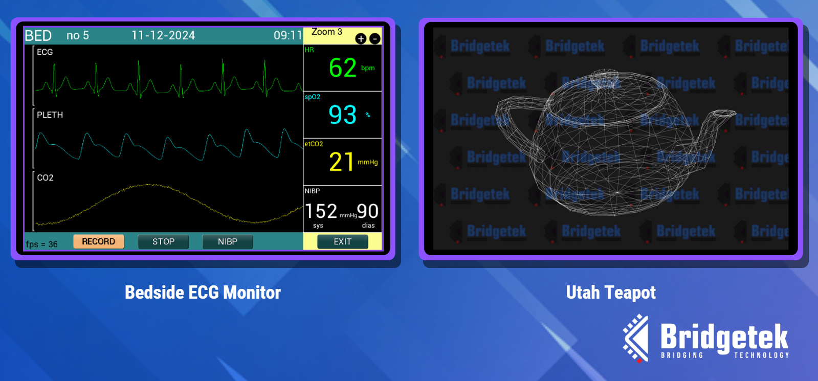
The frame buffer enhances performance for applications such as the bedside monitor and Utah Teapot
One of the main features available on the BT820B is the LVDS video input allowing users to integrate video streams of up to 1920 x 1200 at 60fps on to their displays. An internal real-time video image processing engine on the BT820B can be leveraged by users to apply effects onto incoming video streams via simple command driven operations. MCU resources can be saved by allowing the BT820B to enhance incoming video streams via its video processing capabilities, such as fish-eye effect reduction and gaussian blurs.
Image processing capabilities of the BT820B include:
- Resizing: Easily generate thumbnails from incoming video streams.
- Blurring: Create more appealing user interfaces by blurring the background while keeping the foreground sharp.
- Rotating: Rotate the video easily and apply to shapes (such as cubes) for impressive visual effects.
- Grayscale Conversion: Convert images to black-and-white.
- Special Effects: Including Darken, Brighten, Invert, Thresholding, Contrast+, Contrast-, Solarize, Posterize, Pseudo-HDR, Advanced Pseudo-HDR, and Combined HDR.
- Histogram Generation: Compute and display the image histogram for image analysis.
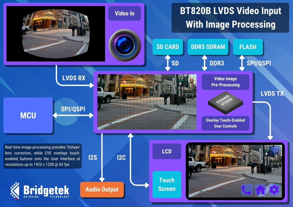
The BT820B’s real-time image processing capabilities include the correction of fisheye lens effect
EVE FAQs - BT88x
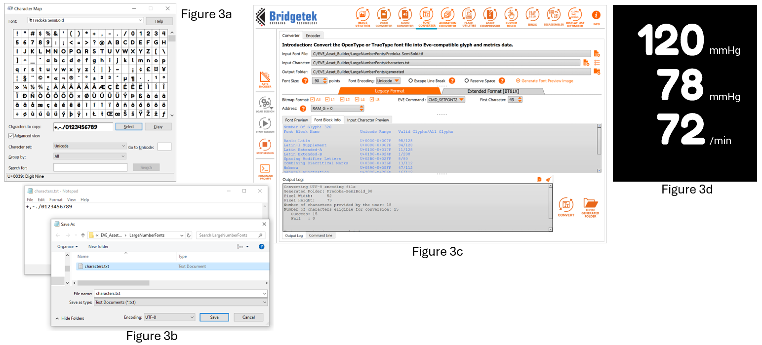
The EVE Asset Builder can be used to convert your chosen font into large characters. You can convert only the numerical characters to save space. Here is one way to do it.
Prepare the font character set:
- Obtain the font file (.ttf or .otf) for the desired font.
- Open the Windows Character Map and select the desired font (the font must be installed in Windows).
- Select the characters to be converted.
- Copy the characters, paste into Notepad, and save the file as UTF-8. (Figure 3b)
Note: We have chosen characters which are continuous in the ANSI character set so that the converted font can be used directly with EVE’s CMD_TEXT and CMD_NUMBER.
Convert the font:
- Open EVE Asset Builder and go to the Font Converter tab (Figure 3c).
- For Input Font, select your .ttf or .otf file.
- For Input Character, select your UTF-8 character text file.
- Here we selected the size as 90, and set the EVE command to CMD_SETFONT2.
- We set ‘First Character’ to 43 to match the first character ‘+’ in our chosen character set.
- Click Convert and once complete, go to the output folder.
- In this example we selected L1, L2, L4 and L8 formats which are converted into output folders of the same name.
- Copy the .raw or the .rawh file (which is a text readable version of the .raw file) for your chosen format into your MCU project as a data array.
Note: L8 offers 8 bits of colour depth but larger data size, whilst L1 offers 1 bit colour depth and smaller data size. In this case, we chose the L2 data which offers 2-bits per pixel.
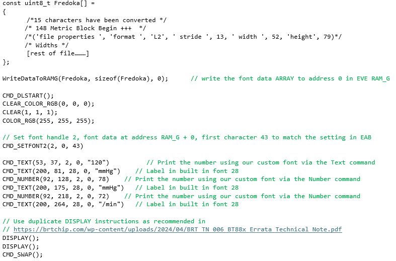
The final display is shown in Figure 3d. The code to set up and use your new font is very simple, as shown below Figure 3.
You can save even more MCU Flash space by compressing the font data. Stay tuned, we’ll show you how to do this in a future FAQ. You can however contact us at support.emea@brtchip.com for any further information on using custom fonts in your application with EVE…”
Here is the full list of commands for the example shown in Figure 3d.
Contact us at support.emea@brtchip.com if you would like an EVE Screen Editor (ESE) project which demonstrates this technique.
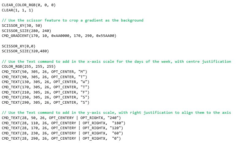
With EVE, you can design and customise your graph easily using the built-in graphics features. Here is one way to do it using the line strip feature.
First of all, we draw the background using a gradient.
- The scissor functions allow the size to be set easily by limiting the gradient to a certain area of the screen.
- In this case, setting the chart height to 240 pixels matches nicely with the scale of the Y axis.
- You can find the list of commands used to draw the graph below Figure 2.
We can then draw the axes:
- Use the Text command to add labels for the X and Y axes.
- We can also use the line feature to draw lines across corresponding to the Y axis labels.
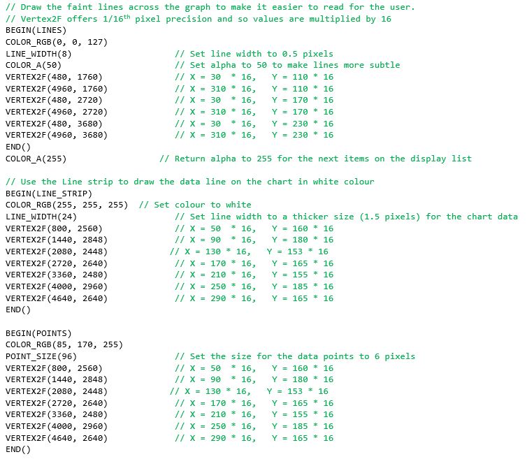
We can now plot the data
- The Line Strip is an ideal solution as EVE will join the vertex points with a line.
- We have a vertex for each data point.
- The EVE Points feature can be used to place a point on each data value using the same coordinates as for the line strip.
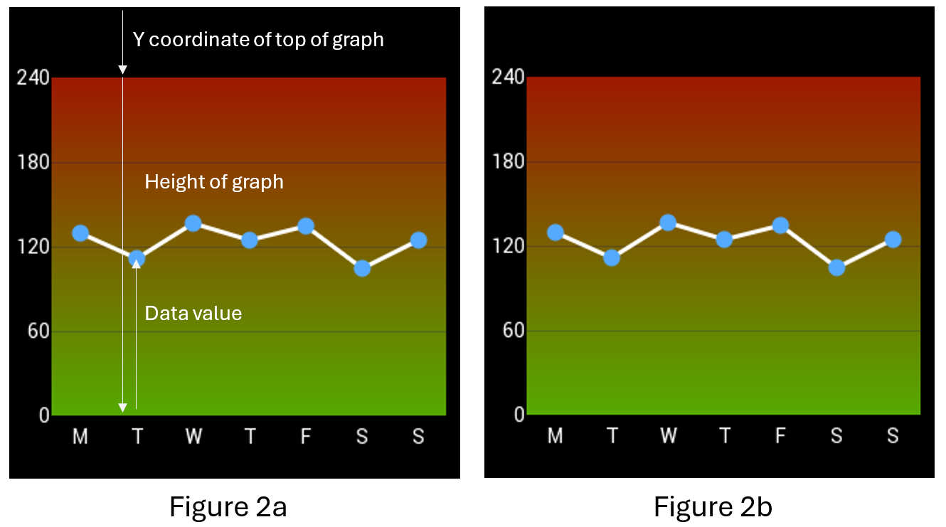
For this graph, the X values match the seven days labelled on the X axis. The Y coordinates for each point can be adjusted to reflect the data values.
Using Tuesday’s data point as an example, the Y value for the vertex command can be calculated as shown in Figure 2a
Note that EVE coordinates begin at (0,0) at the top-left of the screen and that we multiply by 16 as VERTEX2F coordinates have 1/16th pixel resolution.
Y coordinate = ( [Y coordinate of the top of the graph] + [Height of graph] – [Data Value] ) *16
= (50 + 240 – 110) * 16
= 180 * 16
The vertex instruction for the position on the screen is therefore VERTEX2F(90*16, 180*16)
The final graph is shown in Figure 2b
Here is the full list of commands used to draw the graph.
Why not try it out now using our EVE Screen Editor (ESE) tool?
Just download and install ESE using the link above, set the Device Type to BT880, BT881, BT882 or BT883 in the Project window, and paste the code below into the Coprocessor window at the bottom of ESE.
Creating a bitmap may seem like the only solution but EVE’s gradient command can help instead. You can save MCU Flash memory space, BT88X-series RAM graphics memory space and indeed the time needed to create and convert a bitmap by using EVE’s built-in gradient widget.
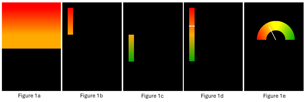
The EVE gradient command renders a smooth gradient from one specified colour to another. However, for some applications we may want to have more control over the colour in certain parts of the gauge and so here we use two gradients. The first gradient for the upper half of the gauge goes from red to amber.
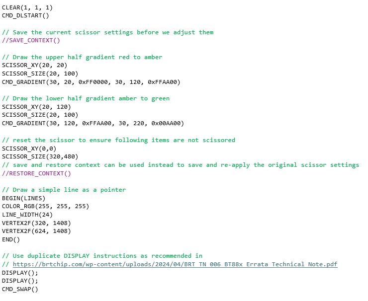
By default, the gradient itself fills the entire width of the screen between the start and end coordinates, and also extends below and above the specified coordinates, as shown in Figure 1a. We can use the Scissor feature to limit the gradient to a specified area: we set the top-left corner at (20,20) with Scissor_XY and then set the size in pixels (20 x 120) with Scissor_Size. Drawing the gradient now fills only the desired area as shown in Figure 1b. The full list of commands used to create the gauge are also shown below Figure 1.
We can then draw the lower half of the gauge using the same technique. This time, we use the same amber colour at the top of the gradient, and fade to green at the bottom as shown in Figure 1c.
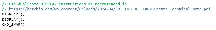
We finish by setting the Scissor_XY back to 0,0 and the Scissor_Size back to the full screen so that any objects drawn after the gauge are not cropped. A save context and restore context can be used instead as shown commented out.
Various methods can be used to add a pointer. In this case a simple white line is used. The Y value of the vertex instructions can be adjusted to make the pointer move up and down along the gradient. Figure 1d shows the final gauge.
EVE Screen Designer has a range of built-in custom gauges that you can add to projects.
You can draw other types of gauges too using this technique such as the arc gauge shown in Figure 1e. Stay tuned, we’ll show you how to do this in a future FAQ. You can, however, contact us at support.emea@brtchip.com for any further information on drawing gauges with EVE…”
Here is the full list of commands used to draw the gauge.
Why not try it out now using our EVE Screen Editor (ESE) tool?
Just download and install ESE using the link above, set the Device Type to BT880, BT881, BT882 or BT883 in the Project window, and paste the code below into the Coprocessor window at the bottom of ESE.
Yes, the BT88x is ideal for using with circular displays. These are available in various sizes such as 2.1” diameter and are great for making digital gauges. The BT88x series includes resistive (BT880 and BT882) and capacitive (BT881 and BT883) touch versions, so you can choose a screen with the best type of touch for your application (or you can use without touch if it is not required). Some panels require the display itself to be set to RGB mode after power-up via a separate serial channel. It is recommended to check the datasheet for your display as if this is needed, some additional pins on the display connector should be connected to your host MCU. Find out more about the BT88x series ICs in the BT88x Datasheet.
The VM880C connects to a host MCU via a 10-way pin header which has power and SPI signals. Since the EVE devices act as an SPI peripheral, you can use any MCU which has an SPI Master. For an existing design, you can connect the module to a spare SPI master on your existing MCU. For new product designs, you can choose the MCU based on the key product requirements (for example, one which has PWM outputs if you will be controlling motors, or one which is low-cost and has a small PCB footprint). The VM880C can also connect to a PC via a USB-SPI cable. See the VM880C datasheet for more details.
Some key requirements for the MCU are:
- An available SPI Master which can be set to SPI Mode 0
- SPI signals used are SCK, MOSI, MISO, CS# (note that CS# can be a GPIO)
- Optional GPIO output for power-down signal
- Optional interrupt input (if interrupt operation is required)
- SPI and GPIO can use 5V or 3.3V signal levels due to the VM880C’s on-board buffers
Both modules allow you to easily evaluate the BT88x series. The main factor in choosing between these modules is which type of MCU host you will use.
The IDM2040-43A has an on-board RP2040 MCU which can be programmed in languages such as C and CircuitPython. The integrated MCU makes this module self-contained with just a USB connection to a computer for programming. Connectors allow access to a range of I/O from the RP2040 such as I2C and GPIO to attach peripheral devices.
- IDM2040-43A can only be used with the on-board RP2040 acting as the host to the BT88x and cannot be used with a different MCU.
- Capacitive touch screen (4.3” LCD integrated into the module)
- Plastic bezel for easy mounting
- Uses BT883 EVE Graphics controller
- See the IDM2040-43A datasheet for more details.
The VM880C is designed for connecting your own MCU and display.
- VM880C module can be used with any MCU/Host which has an SPI Master
- Resistive touch screen such as 4.3” or 5” (LCD not included)
- Credit-card PCB format with 40-way FPC for display and 10-way header for SPI
- Uses BT880 EVE Graphics controller
- See the VM880C datasheet for more details.
EVE FAQs - General
Our BT81x series (BT815, BT816, BT817, BT818) have a Quad-SPI NOR Flash interface. You can store your images on the NOR Flash chip and EVE can then access them directly.
The BT81x can also use the ASTC format which reduces the image size whilst retaining good image quality. The EVE-attached Flash can also store assets such as fonts, video and animations, ensuring that these can all be used even where the host MCU has a small Flash size.
You can use the EVE Asset Builder (EAB) to convert your own custom fonts, allowing you to use large numbers and letters as well as choosing the font style.
EVE has a range of built-in font styles and sizes but some applications may require extra-large fonts. Convert selected characters from your preferred font using EAB to give your elevator panel your desired style and ensure ease of viewing with extra large characters.
With EVE, you can easily improve your user interface with a colour touch-enabled display without stepping up to a higher spec MCU.
Connecting to an available SPI Master on your existing MCU, EVE is easy to add whilst minimising any re-design of the hardware. EVE is also easy to integrate with your software with its simple command set. EVE takes most of the hard work away from your MCU allowing you to create a user-friendly and attractive user interface without needing a high-performance MCU. Touch control can also be implemented with minimal hardware and MCU overhead thanks to EVE’s built-in touch controller engine.
You can also create your own controls such as arc gauges and charts using the EVE graphics features to give your design a unique appearance.
EVE has a range of built-in widgets for common controls such as buttons, sliders and gauges. These make it easy to add controls to your application. However, you can also create your own controls using the EVE display list.
You can even combine built-in widgets with custom designs. For example, the gauge widget is useful as it takes away the need to manually draw and rotate the needle. Drawing the gauge without the background and/or scale allows you to add your own graphics behind to make an attractive custom gauge.
We have examples of custom controls such as arc gauges and charts on our Bridgetek Github page, in the examples in EVE Screen Editor and in EVE Screen Designer.
EVE has a range of features such as audio tone output, a range of image formats for icons, and built-in widgets such as buttons/sliders, which can help with this.
When creating a touch user interface, one way to make it more intuitive is to provide feedback to the user to confirm that their touch was accepted. EVE has a wide range of built-in audio tones which can be selected and triggered with a simple register write and this is an ideal way to show that the touch was detected.
Some EVE widgets (such as the button widget) have a 3D effect which gives an unpressed appearance. You can turn off the 3D setting to make the button flat when a touch is detected on the button, causing the button to appear to be pressed in. Images are also often used as touch icons for custom styling.
EVE’s graphics capabilities make it easy to add effects such as a coloured border around the icon which appears when pressed, to change the colour of an icon when pressed, or even to apply effects such as shrinking the icon slightly to give a ‘pressed in’ effect.
When implementing controls such as cursor and X/Y controls on the screen, one other useful technique is to draw a larger invisible circle behind the cursor and apply a touch tag to that so that the cursor effectively has a larger area.
EVE has innovative touch tagging and tracking features to make it easy to interpret touches on the screen.
With tagging, you can assign tag numbers to objects on the screen when you draw them. When the screen is being displayed, you can check for touches by simply reading a register which will return the tag number if a tagged item is being touched (you can still read the X and Y coordinates of the touch too if required).
This is ideal for controls such as buttons on the screen. You can also enable an interrupt to notify the MCU if the tag value changes.
The main differences between these parts are that the BT882/3 includes a higher colour depth RGB interface (RGB666 vs RGB888), includes an additional GPIO pin (3 GPIOs vs 4 GPIOs) and has an increased package size than that of the BT880/1 (QFN48 vs QFN56).
1.It allows you to use a low-cost MCU for applications with graphical display, touch and audio.
-
- Ideal for upgrading existing products as well as new products.
- Create attractive and well featured HMIs with very light loading on the MCU.
- External flash offloads storage from MCU memory (BT81x).
- Use your preferred MCU – SPI command set allows use with almost any MCU.
2. Having a separate graphic controller provides flexibility.
-
- Have a greater choice of MCUs – code can be easily ported to work with different MCUs.
- Change to a completely different MCU, add the EVE SPI routines, and re-use the same EVE application code saving a lot of cost, time and effort.
3. Bridgetek’s powerful graphical toolchains and code examples make application development easy.
-
- EVE Screen Designer allows the GUI to be developed on a PC and generates code.
- EVE Screen Editor allows users to develop screen content graphically with drag and drop.
- Comprehensive software examples make developing the code easy.
4. Benefit from object oriented operation.
-
- Programming is easy and intuitive.
- Easily add touch using the tagging and tracking features whilst minimising loading on the MCU.
EVE stands for Embedded Video Engine, which is powered by FTDI Chip in-house technology developed for embedded graphics and video applications. It will greatly reduce the development effort as well as the MCU bandwidth required for graphic displays. EVE has 3-in-1 functionality including display, audio, and touch, and in combination with its object oriented methodology makes the creation and rendering of graphics very easy/intuitive while at the same time greatly reducing the system implementation costs.
EVE has many differentiators when compared to GPUs, including:
No external frame buffer integrated touch screen
Simple serial MCU interfaces for controlling and implementing the display, namely SPI, Quad SPI (FT81X only) and I²C
Audio playback with built-in sound synthesizer Backlight LED PWM output
Overall an advanced architecture that provides complete GUI functionality that enables the creation of advanced graphics, while being easy to develop with.
Key features include:
- Built-in graphics operations allow users with little expertise to create high-quality displays Widget support can offload the system MCU and provide a variety of advanced graphic capabilities and efficiencies
- Integrated with a 4-wire touch-screen controller and CTPM through an I²C interface for providing a complete GUI experience Serial interfaces to host MCU with QSPI (FT81X only), SPI or I2C for lower pin count and system cost Programmable interrupt controller provides maximum flexibility with host MCU
- Internal 12MHz oscillator within +/- 5.6% accuracy; integrated clock multiplier and system clock out function (48 or 36MHz)
- Clock switch command to switch internal or external oscillator with 12MHz crystal, or external 12MHz clock input for better clock requirement
- LCD display support for SVGA (800×600) (FT81X only), WQVGA (480×272) and QVGA (320×240) supporting data enable mode and VSYNC/HSYNC modes
- Audio channel output via PWM output Sound synthesizer
- Low power consumption
- Flexible power mode control including power down, sleep and standby states Supports host interface I/O voltage from 1.62V to 3.63V
- Supports extended temperature range, -40 to 85 C, to address a wide range of market applications
- Low internal voltage regulator supplies 1.2V to the digital core, enabling low power operation
The FT8XX functionality provides the highest value and addresses the widest market. The architecture can be scaled and readily partitioned so that other family members can be quickly introduced. In addition, we continuously evaluate market feedback and strategic opportunities prior to publically announcing the EVE roadmap, and appreciate user inputs.
Yes, our partner, MikroElektronika, offers a product, Visual TFT, which supports many of EVE’s capabilities, objects, and widgets. Visual TFT retails for $90-99 and will help customers develop graphic solutions quickly and easily. It will shorten the learning curve dramatically, as the software employs many high level graphic elements that can be readily used and manipulated to create professional looking displays (visit www.mikroe.com for more details).
The display list contains the commands that EVE interprets and processes to generate the display. Each display command typically occupies 4 bytes. The maximum size for a display list is 8KB of RAM.
Widgets are predefined graphic objects intended for a specific display/functionality, like items such as clocks, toggle switches, progress bars, etc. They are used to assist developers in creating the screen shot much easier. Widget styles can also be changed by specifying various parameters appropriate to the widget.
FT80X: 256K Bytes
FT81X: 1M Bytes
EVE can display a bitmap and has the capability to decompress JPEG data (only baseline profile).
FT80X: Decompressed JPEG data by software.
FT81X: Decompressed JPEG data by hardware.
No, EVE has no MP3 decoder functionality.
FT80X- No, but FT80X has the ability to render displays that give the sense of animation. Details for these capabilities and example code are provided in the FT80X Programming Guide.
FT81X- Yes, FT81X supports playback of motion-JPEG encoded AVI videos.
As long as MCU has QSPI (FT81X only), SPI or I2C interface and has the capability to construct display list commands, it can work with EVE. This means that a low end 8 bit microcontroller can be readily used with EVE or because the bandwidth requirements are minimal that the current MCU can be used and the display capability readily added into the architecture/system.
Realistically, as long as the MCU has the memory to construct one 4 byte display command and transfer it to EVE via chip interface, EVE is able to display the graph.
No. The EVE series uses internal widgets supplied with the device. To make additional composite objects would require a function in the controller firmware to construct a display list to send to the FT8XX. This is not the same as using a 4 byte widget.
There are two display list buffers as one buffer is required for editing to create a new display and the other is the one that contains the display list currently being actioned. A swap command is required in the controller code to swap between the editable buffer and the actioned buffer.
Not at this time. The utilities are free examples of converting standard file formats to alternative standard file formats compatible with EVE. As such alternative tools could be sourced by the user for Linux and MAC.
Yes. They will be treated as separate objects. The only limitation is that the files must be small enough to fit in the memory (FT80X: 256kBytes, FT81X: 1MBytes)
No. The output is dependent upon MikroE libraries allowing for an integrated, single source solution to application development.
The EVE family of display controllers output RGB signals for connecting to an RGB display panel. However, you can also add an external RGB to LVDS IC to convert these to LVDS (Low Voltage Differential Signalling). We have one example on our ME817EV board which contains a FIN3385 Flat-Panel Display Link Serializer / De-serializer, allowing it to support RGB or LVDS displays. You can find details of this evaluation board here: https://brtchip.com/wp-content/uploads/sites/3/2022/01/DS_ME817EV.pdf
Yes, this is possible. The FT812/3 and the BT81x series have 24-bit outputs on their RGB interface (8 red, 8 green and 8 blue). However, they can be used with LCD panels which have a smaller color depth. Many displays have 18-bit RGB interfaces (6 lines per color). When using a display with fewer bits per color, the REG_OUTBITS register can be written to set the number of lines per color. See the EVE Programmers Guide for details of this register. When setting a number of bits which is less than the maximum for your EVE family device (for example, setting a BT817 to 6 bits per color instead of 8) note that the output is justified to the upper bits. Therefore, your display’s R5:0, G5:0 and B5:0 would be connected to EVE output pins R7:2, G7:2 and B7:2 respectively. The output lines R1, R0, G1, G0, B1, B0 on EVE would not be used.
EVE FAQs -Interface
EVE has an innovative tagging and tracking feature which makes implementing touch controls easy, including rotary controls. Touch tagging allows you to assign a tag to an object on the screen. You can easily determine which item is being touched by reading the REG_TOUCH_TAG register, either by polling or in response to an interrupt (EVE can generate an interrupt on a change of touch condition)
Tracking extends this feature further via CMD_TRACK. You can set an area on the screen and then determine the relative position of the users touch within that area by simply reading REG_TRACKER. Tracking can support linear and radial modes.
- The linear mode is ideal for sliders and scroll bars, and reports the distance along your defined tracked area from 0 to 65536
- The radial mode is ideal for rotary dials. The tracking value represents the angle of the touch point relative to the object’s centre in units of 1/65536 of a circle. 0 means that the angle is straight down, 0x4000 is left, 0x8000 is up, and 0xc000 is right.
Tagging and Tracking support multi-touch (up to 5 touches) on capacitive touch versions of EVE such as the BT817, with five Tag and 5 Tracker registers (e.g. REG_TRACKER to REG_TRACKER_4) providing the results.
Colour picker controls are often used for mood lighting as well as setting display themes. With EVE, it is easy to create various styles of colour picker based on an image.
EVE stores images in RAM_G for display on the screen. The MCU can read this image data from RAM_G via SPI reads. Since we know the size of the image and the format of the image data (e.g. RGB565 has 2 bytes per pixel with red/green/blue data formatted as RRRRRGGG GGGBBBBB) we can determine the colour of each pixel. By combining this with the position of the user’s touch relative to the image, we can determine the colour of the pixel within the bitmap image that they are touching. The image could be a colour gradient or any other custom image that suits the application.
Sliders can be added to provide further brightness and saturation adjustment of the selected colour. Ensure that the screen is calibrated for most accurate results. EVE’s built-in calibration features allow easy screen calibration.
We have examples of colour picker implementations in our EVE Screen Designer (see Examples > Basic > ColorPicker) and we have further explanations and examples of some colour picker techniques in Application Note BRT_AN_074.
EVE provides full PWM control over the external LCD backlight driver circuitry for a display. You can adjust the screen brightness as desired through simple register writes. This is ideal for applications where the screen brightness may be varied by the user via an on-screen slider, for example, or automatically (by connecting an ambient light sensor to the MCU).
The EVE series of display controller ICs include a BACKLIGHT pin which provides a PWM signal to the LCD backlight driver circuit. The PWM output from this pin is controlled by the REG_PWM_HZ and REG_PWM_DUTY registers. REG_PWM_HZ allows for a valid frequency range from 250Hz to 10000Hz, while REG_PWM_DUTY can be set between 0 and 128 (0 means backlight completely off, 128 means backlight at max brightness). Your application can therefore have full control of the LCD brightness.
You can also turn off the backlight and put EVE into a low power mode when the smart home controller is idle. EVE can pass the interrupt signal from the touch panel to your MCU, allowing you to wake EVE and illuminate the display when a user touches the screen.
EVE includes a range of built-in sound effects such as beeps, bells, clicks and musical instruments which can be played via a simple register write.
These take the hard work out of recording and fine-tuning sounds or even trying to generate professional sounding tones with an MCU. Use touch tags to detect when icons or buttons on the screen are being touched.
Then, write the hex code for your chosen sound to REG_SOUND to play it (see the Audio section of the EVE device datasheet for a table of sounds).
You can also set the volume via REG_VOL_SOUND which is useful for making alert sounds louder and touch acknowledgement more discrete.
Yes, BT815/6 and BT817/8 have features to make animations easy. You can play multiple animations simultaneously. Convert your GIF file(s) using our EVE Asset Builder and then play them on EVE with just a few commands. Store your animation data on EVE’s directly attached NOR Flash to minimise Flash usage on your host MCU. BT817/8 has some new animation features, allowing you to play animations from RAM_G and CMD_RUNANIM which makes animations even simpler to play.
Many capacitive touch panels (CTP) have adjustable sensitivity. In this case, you can use our custom touch feature to configure this by writing to the registers of the CTP. This will help to ensure a good user experience with your touch interface. Check the datasheet for your CTP to find out which settings it supports. Custom touch is available on BT881, BT883, FT811, FT813, BT815, BT817 and BT817A. Find out more in our capacitive touch guide BRT_AN_090.
The newest generations of EVE ICs (FT81x, BT81x) support the implementation of custom touch controller firmware to support a wider variety of Capacitive touch controllers. Custom touch controller firmware can be compiled using our EVE Asset Builder (https://brtchip.com/eab/) toolchain, where instructions on how to load this firmware during EVEs boot sequence are also included. Please see BRT_AN_090 Eve Working with Capacitive Touch Screens (https://brtchip.com/wp-content/uploads/2025/02/BRT_AN_090_EVE_Working-with-Capacitive-Touch-Screen.pdf) for more details.
EVE displays items on the screen in the order of the display list. Therefore, items further down in the display list will be layered on top of items further up. A shape or image displayed towards the end of the list can therefore be overlaid on top of the earlier screen contents. This is useful for adding a menu or message box over the top of the user interface. You can use the Alpha setting (COLOR_A) to give the message box partial transparency too for an improved visual effect.
Some icons may have a specific outline shape or may have areas inside where you want the background to show through. You can help make your interface more intuitive by using images as icons for status indication and for touch buttons. Ensure that your original image is in a format supporting transparency. You can load transparent PNG images to EVE using CMD_LOADIMAGE or you can convert them using EVE Asset Builder (https://brtchip.com/eab/). When converting the images, ensure that you convert to a format supporting transparency (alpha) such as ARGB1555 or ASTC.
FT80X: Standard serial interfaces to the host MCU include: SPI up to 30MHz or I²C clocked up to 3.4MHz.
FT81X: Standard serial interfaces to the host MCU include: QSPI up to 30MHz.
EVE can be designed into a system without the need to add an external crystal component. EVE has an internal oscillator that is enabled by default upon power on. The frequency of the internal oscillator is 12MHz ±5.6% across the operating temperature (-40° to 85°C).
When external crystal component is used, the crystal component should be 12MHz.
These connectors are 2×8 way Micro-MaTch connectors and allow for expanding the IO of the VM800P to add interfaces such as Ethernet, RS485, relays etc. via the SPI port of the ATMEGA328P.
No. For designs requiring additional memory for storing objects such as images and audio files the additional memory must connect to the MCU. This allows for extra flexibility as the MCU can access the memory for other non-EVE associated files without going via the FT8XX and as such, the extra system memory becomes general purpose. This architecture also allows for the additional memory to be either USB, SD Card or other formats.
No. Current device in the series are designed for RGB only
Yes. The FT8XX contains a function called swizzle which allows the assignment of the Red, Green and Blue data lines to be changed. The user can either swap an entire bank of colour pins or reverse the bit order. To make the swaps the application code must access the REG_SWIZZLE register.
No, the raw touch screen information is acquired, processed and updated in the respective register for the MCU to read. EVE does the noise filtering for the resistive touch-screen. The x, y data is loaded into registers to be read by the MCU. In addition, a resistive location can be defined and mapped to a specific character (i.e. a specific alpha-numeric) so that this specific character is transferred from the FT8XX to the MCU, such that the MCU need not execute any parsing functions.
Essentially yes. The FT8XX at its most basic level can be considered as a QSPI (FT81X only) or SPI peripheral to a host controller. Whether that host is in the MCU or FPGA is up to the designer.
Although each instruction is sent over QSPI (FT81X only) or SPI interface, this cannot be guaranteed as not every instruction does the same thing. E.g. some instructions must fetch objects from object RAM while others draw primitives on the fly. Widget instructions are like zip files which must be extracted to create a full list of commands for the display list.
The same SD Host Controller is in the FT93x and FT90x. Our measured speeds are (Class10, 16KB Cluster, FAT32): FT930, SDCLK@25MHz USB Read (100MB): 9.7 MBytes/sec USB Write (100MB): 6.8 MBytes/sec FT930, SDCLK@50MHz, Class10 USB Read (100MB): 18.5 MBytes/sec USB Write (100MB): 8.0 MBytes/sec.
EVE FAQs – Power
On power up, EVE is in STANDBY state. A dummy read at location 0 from the host interface will send EVE from STANDBY state to ACTIVE state.
There are 4 power modes that EVE supports.
- Active state – EVE is in full function mode performing graphic rendering, touch processing and audio processing.
- Standby state – in this state, the crystal oscillator and PLL are functioning, and the system clock to EVE’s core is disabled. All register content is retained.
- Sleep state – in this state, the crystal oscillator and PLL are disabled, and the system clock applied to EVE’s core is disabled. All register content is retained.
- Power down state – in this state, the internal 1.2V regulator supplying the core digital logic is disabled. The crystal oscillator and PLL are disabled, and the system clock applied to EVE’s core is disabled. All register contents are lost and reset to default upon power on reset.
EVE FAQs – Display
EVE has several features which can help you maximise battery life. Many In-Home Displays for Smart Meters (and smart meters themselves) use battery power for portability (or due to the lack of a power source nearby). A combination of reducing the current drawn by the display and audio, putting EVE into low power modes and putting the MCU into low power modes can help maximise battery life.
One way to save power, even during use, is to dim the display via the backlight Pulse Width Modulation output. Your MCU could use an ambient light sensor and dim the backlight when full brightness is not needed, or it could have a slider on the EVE display itself to adjust brightness.
When the In-Home Display is idle and the display can be blank, the following steps can help to reduce power:
- Turning off the backlight completely by setting the REG_PWM_DUTY register to 0
- Setting all RGB output pins to low. This can be achieved by putting EVE into Power Down mode. If putting EVE into Standby/Sleep modes, the host MCU can set the RGB pins (including HSYNC/VSYNC/PCLK/DE/R[8]G[8]B[8]) to low by setting REG_HSYNC1=REG_HSYNC0 and REG_VSYNC1=REG_VSYNC0 and setting REG_PCLK=0
- Setting the capacitive touch panel controller (CTP) to a low power mode. For Focaltech CTPs this can be done via the ‘low-power mode’ bit in REG_TOUCH_CONFIG. For other CTPs, EVE’s custom touch feature can be used to implement the sleep/wakeup according to the CTP protocol found in its datasheet.
- Disable the external audio amplifier by selecting its low power mode via a GPIO from EVE.
- Disable the carrier wave on the EVE audio output pin by playing the mute sound via the sound registers.
The In-Home display can be woken up when the user touches the screen or when the MCU receives important data to display. The EVE Interrupt pin allows the MCU to easily determine when the screen has been touched.
Note: Capacitive Touch Panel controllers often have several modes with different current consumptions (e.g. active, monitor and sleep). They may not detect touches in some low power modes, check the datasheet of your selected touch controller.
Although the display (and audio) can account for most of the current, EVE also has low power modes which reduce the consumption of the IC itself to a minimum. Several modes are available to allow the best combination of power saving vs start-up time/actions to be chosen for the application. These include the following modes (check the datasheet for your EVE device for specific details)
- Standby: The system core clocks are disabled but the crystal oscillator and PLL remain on and the register contents are retained.
- Sleep: The system core clocks, crystal oscillator and PLL are all disabled. The register contents are retained.
- Powerdown: The system core clocks, crystal oscillator and PLL are all disabled for even lower power. All register contents are lost and reset to default when the chip is next switched on.
The EVE Interrupt pin can be used to indicate touches to your MCU even when EVE is in low power modes, allowing the MCU to wake the display when the user interacts with the screen.
Touch screens normally report x and y coordinates corresponding to the position of the touch on the screen (via I2C for capacitive touch and via resistance values for resistive). Traditionally, the process of decoding touch coordinates reported by the panel, transforming them to match the screen dimensions and alignment, and then working out which (if any) item on the screen is within the area being touched can be complex and time-consuming for the main MCU controlling the display.
EVE is integrating an innovative touch engine which does all this hard work, making it much easier to add resistive or capacitive touch control to your application. One key feature, which helps to reduce the workload of both the MCU itself and of the application developer, is Touch Tagging. Instead of manually comparing the coordinates to those of items on the screen, you can simply assign tag values when creating your screen layout as a display/co-processor list. Items drawn on the screen are assigned a tag number based on the last specified tag before them in the display list. Then, the MCU can simply read EVE’s REG_TOUCH_TAG register (either by polling or in response to an Interrupt from EVE) to determine which item is being touched.
However, there may also be items on the screen that you do not want to tag. For example, a bitmap or shape behind a group of tagged buttons/icons or text labels beside the buttons. You can use the TAG_MASK instruction to stop items being tagged. We illustrate this here with a simple example.
The tag buffer (which has a value for each pixel) is cleared to a default or specified value when you clear the screen (in the example below we set Clear_Tag as 128).
- Tag_Mask = 1 enables tagging: When you draw an object, the tag buffer in the area of the object (button, text etc.) will be updated with the last tag set above in the display list
- Tag_Mask = 0 disables tagging: When you draw an object, the tag buffer is not updated with a new tag value
The simplified code example below shows the actual tag number which will be read back from REG_TOUCH_TAG when each object is touched
- No touch on the screen: REG_TOUCH_TAG = 0
- Touching the buttons or text: See the comments for each line of code
- Touching any other area of the screen: REG_TOUCH_TAG = 128 (as set by CLEAR_TAG)
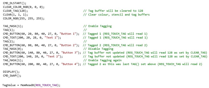
Note that the REG_TOUCH_TAG register is updated once the pixels for a given frame are fully scanned out. We use buttons and text here but the same applies to other objects such as shapes and images. The capacitive versions of EVE support up to 5 simultaneous touches and so have 5 different REG_TOUCH_TAG registers allowing the tag for each touch to be read.
No, EVE does most of the hard work to render your colour graphics and so a powerful MCU is not needed. This also allows your MCU to do other tasks such as processing the meter data or talking to remote metering equipment over a wireless link.
Some features of EVE which help minimise the MCU’s workload include:
- EVE’s efficient command-based screen creation allows complex graphics with minimal MCU workload and SPI traffic
- Using built-in widgets such as gauges, gradients and buttons further reduces this, allowing user controls to be created easily without complex graphical operations or calculations
- Your MCU only needs to send a new display list when the screen content changes (no need to refresh the screen constantly)
- Store sections of the display list in EVE’s RAM for parts of the screen content that do not often change and recall them using the APPEND command
- On BT817/818/817A, you can now also store sections of co-processor lists and recall with the CALLLIST command for even greater flexibility
Use EVE’s interrupts to tell your MCU when a touch event has occurred, and use touch tags to easily determine which item was touched
For SVGA (800×600) (FT81X only), the refresh rate is 60Hz (typical configuration).
For WQVGA (480×272), the refresh rate is 60Hz (typical configuration). For QVGA (320X240), the refresh rate is 60Hz (typical configuration)
Depending on the display panel requirement, other values of refresh rates can be configured by adjusting PCLK_DIV, HCYCLE and VCYCLE registers.
EVE supports LCD displays such as SVGA (800×600, FT81X only), WQVGA (480×272) and QVGA (320×240) available in the market. Data enable and VSYNC/HSYNC modes are also supported to provide flexibility for the various displays on the market.
FT80X supports video RGB, parallel output (default RGB data width of 6-6-6) with 2 bit dithering; configurable to support resolution up to 512×512 and LCD R/G/B data width of 1 to 6.
FT810/FT811 support video RGB, parallel output; configurable to support resolution up to 800×600 and LCD R/G/B data width of 1 to 6.
FT812/FT813 support video RGB, parallel output; configurable to support resolution up to 800×600 and LCD R/G/B data width of 1 to 8.
Signals required are R [7:2] or [7:0], G [7:2] or [7:0], B [7:2] or [7:0], PCLK, DE, VSYNC and HSYNC. R, G, B signals locations are user configurable. In addition, endian of R, G, B signals are also configurable. These will make PCB routing much easier.
Yes, EVE has a PWM output that is used to drive backlight LED drivers. It supports fully on, off and dimming the backlight.
There is no specific requirement on what type of backlight drivers are to be used. It normally depends on the LCD/LED specifications. The back light driver in FT8XX design is the MIC2289-34.
The fading is really controlled by the MCU controlling EVE. The fade affect is related to the alpha value of the icon (bitmap).
static void showhome()
{
if (!screen.snapshot && homefade) {
VC.command(COLOR_A(min(255, homefade * 3)));
static PROGMEM prog_uint32_t std1[] = {
TAG(TAG_HOME),
LINE_WIDTH(48),
BEGIN(RECTS),
COLOR_RGB(0,0,0),
VERTEX2II(4, 4, 0, 0),
VERTEX2II(6+32, 6+32, 0, 0),
COLOR_RGB(255,255,255),
VERTEX2II(5, 5, 0, 0),
VERTEX2II(5+32, 5+32, 0, 0),
BEGIN(BITMAPS),
COLOR_RGB(0,0,0),
VERTEX2II(5, 5, 14, 0),
};
MEMCMD(std1);
}
endframe();
}
The value of “homefade” is affected by touch events on the screen.
Yes. Treat each character to be displayed separately. This will allow a unique font to be applied to the character whether it is a number or a letter.
No. Calibration should be done at least once (manufacture/first use) and after that the calibration values may be stored to internal non-volatile memory for use in subsequent power-ons as per the example below.
// If the EEPROM starts with byte 0x7c, then it already holds
// the 24 byte touchscreen calibration values.
if (istouch() || (EEPROM.read(0) != 0x7c)) {
blank();
while (istouch())
;
VC.wr(REG_PWM_DUTY, 128);
MEMCMD(start_clear);
VC.cmd_text(screen.w/2, screen.h/2, 28, OPT_CENTERX|OPT_CENTERY, “please tap on the dot”);
BLK_START
CMD_CALIBRATE,
0
BLK_END
VC.waitidle();
for (int i = 0; i < 24; i++)
EEPROM.write(1 + i, VC.rd(REG_TOUCH_TRANSFORM_A + i));
EEPROM.write(0, 0x7c); // is written!
}
else {
for (int i = 0; i < 24; i++)
VC.wr(REG_TOUCH_TRANSFORM_A + i, EEPROM.read(1 + i));
}
Rectangles are drawn with the primitive command RECTS. To adjust the appearance of the corners call the command LINE_WIDTH before drawing to the rectangle to adjust the corner radius.
A logo is simply a picture (bitmap). As such it should be treated no differently than any other bitmap.
Create your image and size it using PC tools such as paint or GIMP. Use the image conversion utility to convert to a format that is suitable (higher resolution = more memory) and load the image. See the examples page for code examples e.g. Example 6 – Image Viewer.
EVE FAQs – Touch
FT800/FT810/FT812 supports 4-wires resistive touch-screen controller that incorporate median filtering and touch force sensing.
FT801/FT811/FT813 supports I²C capacitive touch screen with up to 5 touch detection.
Please refer to this link for detailed description on how a 4 wire resistive touch screen works. http://www.sparkfun.com/datasheets/LCD/HOW%20DOES%20IT%20WORK.pdf
Please refer to this link for detailed description on how a capacitive touch screen works.
https://www.youtube.com/watch?v=BR4wNq6WGkg
Yes. Touch pressure measurement can be detected on FT800/FT810/FT802.
FT800/FT810/FT812 are resistive touch solution, there is no multi touch support.
FT801/FT811/FT813 are capacitive touch solution which support 5 touch detection.
Yes, users can drag a screen slider with a stylus or finger.
Refer to the App Note AN_336 FT8xx-Selecting an LCD Display section 6 for a list of compatible touch controllers.
EVE FAQs – Audio
EVE outputs the audio signal via the Audio_L pin. This goes into an external amplifier circuit and then on to the speaker. Many development modules for EVE include the amplifier on the PCB and either an on-board speaker or a connector for an external speaker. Here are some things to check:
- Check all connections and that the external speaker (if used) is of a suitable impedance for the amplifier used
- Check that any jumpers on the board are set to power up the amplifier
- Check that the power source used has sufficient current capability (due to the display backlight and audio circuit, the overall display module can require quite a lot of current, often several hundred milliamps or more)
- Ensure the audio amplifier is not in the power-down state. Many evaluation modules have a power-down signal controlled by a GPIO line on EVE to power down the amplifier when not used. Check that the GPIO and GPIO Direction registers in EVE have this GPIO line set as output and to the correct state to enable the amplifier.
- Ensure the volume has not been turned down. Volume is controlled by REG_VOL_SOUND for sounds and REG_VOL_PB for playback of audio. A value of 0xFF is the highest while a value of 0x00 is muted.
EVE supports audio wave playback for mono 8-bit Linear PCM, 4-bit ADPCM, and μ-Law coding format at sampling frequencies from 8kHz to 48kHz.
The audio output is a PWM signal that goes through 3 stage of filtering to generate the final analogue audio signal. The signal to noise ratio is 46db.
The output audio from EVE is mono.
48KHz, up sampled if source is not 48Khz.
Yes, EVE has 8 bit resolution volume control.
MCU FAQs -General
Yes, the IDM2040-43A incorporates a Raspberry Pi RP2040 as its host MCU which includes a pinned out UART interface. This interface can be used in conjunction with our IDM-RS232 and IDM-RS485 daughterboards to provide RS232 and RS485 connectivity to the IDM2040-43A.
The BT880 supports a wide variety of LCD screen sizes through customisable display setting registers, popular LCD sizes supported include: QVGA (320*240), WQVGA (480*272) and HVGA (480*320) resolutions. The maximum number of pixels supported per line is 2048, allowing for the use of Bar-Type displays with the BT880 such as 800×160 or 1024×120 resolutions. If you have any queries concerning LCD support for the BT880 please contact support.emea@brtchip.com
The audio out pin will normally output a carrier wave even when no sound is being played. To stop this, you can play the MUTE sound by writing 0x60 to the REG_SOUND register.
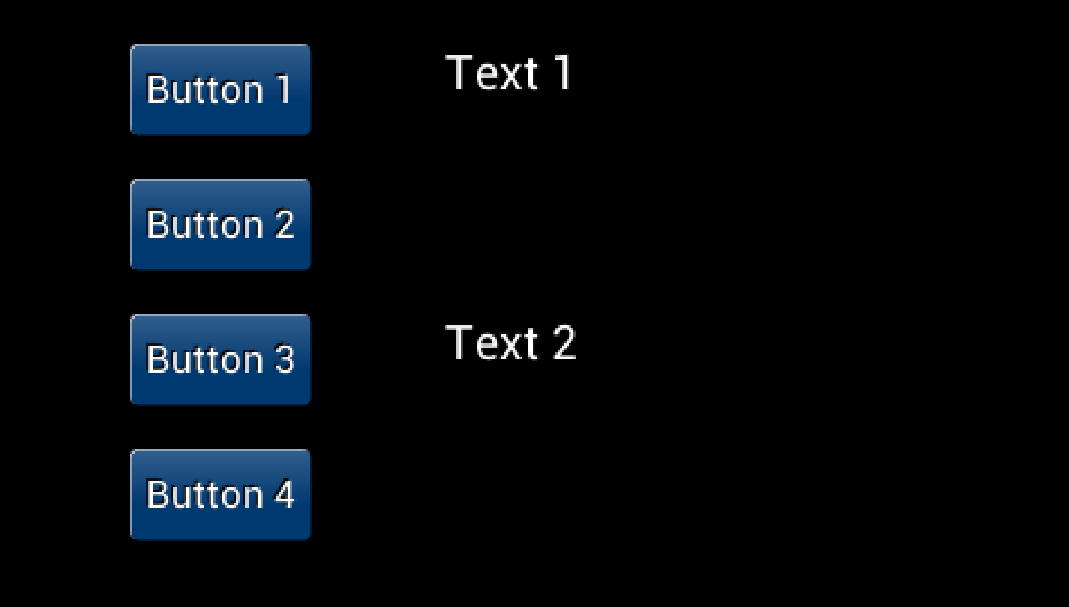
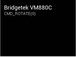
Yes, the VM880C is ideal for prototyping your new portrait or landscape oriented application. The VM880C uses the new BT880 Display/Touch/Audio controller from Bridgetek.
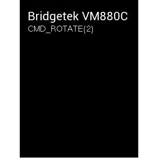
The BT880 includes a screen rotation feature. By calling the CMD_SETROTATE, you can set one of seven different screen orientations. Therefore, you can use a landscape panel in a portrait orientation without any complex software-based rotation.
CMD_SETROTATE will rotate both the screen content and the resistive touch so you can have the full touchscreen functionality in each different orientation. The screen can also be rotated by writing the same value directly to REG_ROTATE but this does not rotate touch, and so using CMD_SETROTATE is recommended.
The CMD_SETROTATE offers the following options:
0 is for the default landscape orientation
1 is for inverted landscape
2 is for portrait
3 is for inverted portrait
4 is for mirrored landscape
5 is for mirrored inverted landscape
6 is for mirrored portrait
7 is for mirrored inverted portrait
The BT880 and BT881 are a new series in the EVE family of devices which are ideal for applications using displays of up to 4.3” and 5”. With many of the features of the FT81x series such as screen rotation for portrait orientation, they offer a cost-effective solution for applications using screens with resolutions such as 480×272, 320×480 and 320×240. The BT880 and BT881 offer a 6+6+6 18-bit RGB interface with resistive (BT880) and capacitive (BT881) touch.
The MM900EV modules provide an easy way to evaluate the FT90x series of microcontrollers. It is recommended to use the UMFTPD2A module along with your MM900EV module so that you can carry out debugging and flash programming from the FT900 Toolchain. We also provide a wide range of examples which are installed with the toolchain. Many of these examples provide debug print outputs via the UART of the FT900 and some examples (such as the UART ones) send and receive data over the UART. One easy way to receive and send data over the UART is to use the spare UART port on the UMFTPD2A. This uses channel 3 of the on-board FTDI FT4232H USB-serial interface.
You can connect the UART lines from the MM900EV1B to the lines on the UMFTPD2A J2 connector.
Using the MM900EV1B as an example, and using UART0 on the FT900, the connections would be:
UMFTPD2A J2 pin 1 (GND) to MM900EV1B CN3 pin 2 (GND)
UMFTPD2A J2 pin 2 (CTS#) to MM900EV1B CN3 pin 8 (RTS#)
UMFTPD2A J2 pin 3 (leave unconnected)
UMFTPD2A J2 pin 4 (TxD) to MM900EV1B CN3 pin 6 (RxD)
UMFTPD2A J2 pin 5 (RxD) to MM900EV1B CN3 pin 4 (TxD)
UMFTPD2A J2 pin 6 (RTS#) to MM900EV1B CN3 pin 10 (CTS#)
Once the UMFTPD2A is connected to the PC and ready (showing under Universal Serial Bus Controllers and Ports sections in Device Manager) you can open port C from a standard terminal program such as PuTTY. The module will normally appear as four consecutive COM ports e.g. USB Serial Port (COM4) to (COM7). The spare UART port C will normally be the third one and so COM6 in this example. Set the baud rate to match the one used in the FT900 example code and open the port and you can now easily communicate with the UART without needing a separate serial device.
.
You can purchase via our Web Shop and Sales Network.
No, this has no impact on VNC2. We see all families offering excellent value with the common thread that they possess key USB features.
- VNC2 offers 2 x USB2.0 Hi-Speed ports which can be configured as Host or Device
- FT51A offers USB device and hub functionality
- FT900 provides 1 x USB2.0 Hi-Speed host and 1 x USB2.0 Hi-Speed device.
Needless to say, with the FT51A and FT900 we have targeted high performance with features that are key to overall system value.
The FT900 and FT51A provide complete library API source code, unlike the VNC2, giving more flexibility to the developer.
Yes. The FT51A is fundamentally an 8051 and the register map reflects that. This should enable a small learning curve for customers already familiar with 8051 designs.
The FT900 is all Bridgetek proprietary, but the register map as well as sample code and drivers are available. The FT32 core technical manual is available under NDA.
Eclipse was chosen as an industry known, open source IDE that we can simply expand with our plug-ins for the debugger /firmware upload features. So it’s free for all to use.
Expanding an existing tool enables a faster time to market, whilst also presenting a familiar interface for existing Eclipse users again making the learning curve for these new devices shorter and shallower.
If you are looking for a more mature environment, please see the tools available from MikroElektronika. They will provide hardware and an IDE (Integrated Development Environment) for both the FT51A and FT900 devices.
GCC which is used for FT900 does not support FT51A devices. Hence different compilation tools were required (FT51A uses SDCC). However both can be used with the Eclipse IDE.
The only price you will have to pay is for the IC itself and the development modules, if required. The IDE, API library, example code and technical support is totally free enabling quick application development!
Yes, full source code is provided to allow users full control and allows modifications for example. Users simply have to include the source file into their project to over-ride the pre-built library.
MCU FAQs – FT51A
44 pin LQFP and 48 pin WQFN = Full spec (1 x USB upstream, 1 x USB downstream, 16 digital pins, 16 analog pins)
28 pin SSOP and 32 pin WQFN = Reduced spec (1 x USB upstream, reduced digital and analog pins)
Note: Firmware can change the pin mapping through IOMUX programming.
Firstly, the 8051 core we have selected is one of the fastest currently available.
Secondly, with the package options we offer from 28 pin SSOP to 48 pin QFN, we offer excellent choices for board area and cost.
Third is the USB hub feature, which you will not find elsewhere. This allows for cascading FT51A devices creating a network of sensors and control boards or connecting alternative USB peripherals to your 8051 core.
- USB Data Acquisition
- General Purpose Microcontroller
- Sensor control
- Mass data storage for medical, industrial and test instrumentation
- USB to RS232/RS422/RS485 Converters
- POS Systems
- Fitness Equipment
- Smart Home Control
- Weather Station
- Keyboard with USB mouse port
- USB Barcode Readers
We provide FT51A Modules which includes evaluation modules and debugger module.
The FT51A can provide a USB DFU interface, meaning that if you connect the USB device controller to a PC, you can use some simple software to update the firmware over USB, meaning that additional programming hardware is not required.
The “blank” chip Bridgetek ship includes a DFU code programmed. However example source code is available to allow users to add this DFU interface to their application code.
This is user defined as it depends on firmware. We provide plenty of examples at FT51A Examples, also provided with the toolchain.
Operating Supply Current in normal operation (48MHz): 20mA typical (maximum 28mA).
Operating Supply Current in USB Suspend (internal clock stops): 150uA typical.
There is no OS needed for FT51A.
Yes, we provide a couple of examples which connect FT51A with EVE. Source code is available with the FT51A toolchain:
- FT51A Sensors Example
- FT51A Spaced Invaders Example.
MCU FAQs – FT90x
We saw performance as a feature that could differentiate Bridgetek Chip from others in the market, especially in applications such as multimedia. The FT900 is a true 0 wait state solution even at maximum core clock speed (100MHz) offering performance of 3.1DMIPs/MHz. As a result, designers can have a blazing fast chip coupled with excellent connectivity options such as Ethernet, USB, CAN bus, as well as a camera interface.
| Package: QFN/LQFP | CAN | Ethernet | Camera | SD | I2S | Others* | |
| FT900Q/FT900L | 100/100 | Y | Y | Y | Y | Y | Y |
| FT901Q/FT901L | 100/100 | – | Y | Y | Y | Y | Y |
| FT902Q/FT902L | 100/100 | Y | – | Y | Y | Y | Y |
| FT903Q/FT903L | 100/100 | – | – | Y | Y | Y | Y |
| FT905Q/FT905L | 76/80 | Y | Y | – | – | – | Y |
| FT906Q/FT906L | 76/80 | – | Y | – | – | – | Y |
| FT907Q/FT907L | 76/80 | Y | – | – | – | – | Y |
| FT908Q/FT908L | 76/80 | – | – | – | – | – | Y |
No CAN – reduces cost (no licence)
No Ethernet – reduces power (has dedicate regulator)
No Camera/SD/I2S – reduces pin count
*USB Host, USB Peripheral, SPI, UART, ADC, DAC, I2C, PWM, RTC, Timers/Watchdog, Interrupt Controller
We provide FT90x Modules which includes evaluation modules and debugger module.
EVE 2 Modules easily connect FT900 with EVE.
- Home Automation Systems
- Home Security Systems
- Enabling Hi-speed USB Host or Device capability within an Embedded product
- Set-top box applications (e.g. USB tuner)
- Industrial control and medical system applications
- Embedded Audio applications
- IP-Camera
- VIOP phone
- Data acquisition systems
- Industrial Control
- MP3 Player
I2S (Inter-IC Sound), is a serial bus interface standard used for transferring digital audio.
Power down current – 700uA (approx.)
Idle current – 42mA (approx.)
Normal operating current – 100mA (varies depends on what peripherals are being used)
32 bit MCU / ARM –typically TI, ATMEL, ST products.
Yes, an accelerometer is just a peripheral chip like any other.
An open source real time OS FreeRTOS is available.
Bridgetek has ported lwIP to the FT90x.
lwIP (lightweight IP) is a widely used open source TCP/IP stack designed for embedded systems.
This is available with some example Ethernet bridging applications in the FT90x Examples page.
Yes, Bridgetek has produced an example FT90x UART to FTDI’s FT232 Host Bridge application.
This example demonstrates bridging an FTxxx class device (e.g. FT232R, FT-X Series) present on the FT90x USB host port to a UART interface, with data transferrable in both directions.
Note: since the USB commands that are used in order to control FTxxxx devices would be exposed, the library is provided as precompiled.
Bridgetek has produced examples showcasing how to use EVE with various host controllers including the FT90x.
Please navigate to the Support –> Software Examples –> EVE Projects on our website for more information.
The FT9xx can be accessed through DFU in three main cases:
- If the Flash has no application firmware programmed: FT9xx devices are supplied with the DFU code already included. Because the Flash has no application firmware, the device will enter DFU mode on start-up and will appear as a DFU device when connected to a computer. This is one approach for initial application firmware programming to be carried out in a production environment.
- When programmed with the main application in the field: Once the FT9xx is programmed with application firmware and is out in the field, DFU offers an easy way to do updates. A DFU code module can be included in the application firmware to support this. The DFU can be activated in several ways including:
-
- On each start-up: The FT9xx will appear as a DFU device for a period specified in the DFU code module (e.g. 5 seconds). During this time, the firmware update application on the computer can capture the DFU and begin communication with the bootloader.
- Always active: The DFU is always active and will appear as a DFU endpoint which can be opened at any time by the firmware update application on the computer
- Application code (via GPIO etc.) activation: The application code can activate the DFU. For example, this could be via the state of a GPIO connected to a pushbutton allowing the user to manually activate DFU
- If the Flash checksum fails: On power-up, the FT9xx verifies the flash against the checksum. In the event of failed programming, flash corruption or if an application error results in flash being written without updating the checksum, the checksum will fail and DFU will be activated, allowing the flash to be reprogrammed.
In order to provide DFU updates in the application, the following requirements must be considered:
- Device Side: The application firmware developed in the Eclipse IDE must include the DFU code module. The Bridgetek FT9xx Programming Utility (part of the FT9xx Toolchain) can be used to prepare a DFU compatible version of the resulting binary file by adding the required DFU Suffix. This binary can then be sent to the FT9xx over DFU by the firmware update application (refer to the Computer Side bullet point below). If the main application uses the FT9xx as a USB device already, the DFU will appear as an additional USB endpoint. If the application does not normally act as a USB device, the USB connector can be provided in the harwdare design to allow for it to be used for device firmware updates.
- Computer Side: A suitable application must be provided to the user which will perform the firmware update over DFU. Bridgetek provides the FT9xx Programming Utility (part of the FT9xx Toolchain) which includes a range of programming tools via a graphical user interface but this is not intended for consumers and end-users. Developers can create a user-friendly end-user application or integrate this functionality into their main application software. The functions in Bridgetek’s command line FT9xxProg.exe utility (which is also included with the toolchain) provide a simple way of opening and programming the device over DFU and can be called from the application. The firmware file can be provided to users to download or can be included in an application package, allowing users to perform the update later with no internet connection.
Note: The DFU supports programming but not debugging of the FT9xx. DFU is not recommended as the exclusive interface for the application development phase as DFU can be overwritten, should a version of the application code which does not include the DFU be accidentally programmed.
The Bridgetek UMFTPD2A Programming/Debug module is recommended for development as it supports debugging and provides access even when the DFU is not included in the application firmware. Providing a connector for the UMFTPD2A (or a PCB footprint) on production boards also allows access in future.
Note: Users should take care if preparing their own DFU firmware image manually. Bridgetek provide the FT9xx Programming Utility which helps users create their firmware image for use with DFU. This tool checks the prefix and that the firmware file is of the correct size for the FT90x or FT93x. It is also possible to prepare a flash image manually using the associated dfu-util and dfu-prefix tools. If doing so, the user must ensure that their firmware is not larger than 252KB for FT90x and 124KB for FT93x to avoid the bootloader at the end of the flash being corrupted. Also, the FT90x/FT93x will enter DFU mode continuously if the application checksum is not calculated correctly or if the FTDI ID byte (0x03 0x04 crc-0 crc-1) is not present at the end of the application partition.
For more information on the DFU and Bootloader, see https://brtchip.com/wp-content/uploads/2024/07/BRT_AN_063_FT9xx_Programming-Debugging-and-Troubleshooting.pdf
The FT90x device can emulate an FTDI D2XX device to the host PC and the data is sent back and forth on the D2XX channel, between a terminal PC application (for example) and the User Firmware application.
The default USB settings like VID, PID, Manufacturer and Serial Number can be changed using the FT900 Programming GUI Utility’s D2XX tab. See AN 365 FT9xx API Programmers Manual and AN 360 FT900 Example Applications for more information.
Yes. Examples are provided which connect to the Android via Android Open Accessory (AOA). This means that the FT90x USB Host enumerates the Android device. See AN 365 FT9xx API Programmers Manual and AN 360 FT900 Example Applications for more information.
Bridgetek has been working closely with 3rd party partners in order to offer additional design aids. A collaboration with MCCI® Corporation, a leading developer of USB drivers and firmware for embedded SoC has resulted in the availability of TrueTaskВ® USB, an embedded USB host stack designed for use with the FT90x MCU product family, and a partnership with MikroE has culminated in providing a comprehensive development environment for the FT90x including compilers, development boards, useful examples for click boards and Visual TFT software support. For more information on MCCI and MikroE, please visit www.mcci.com and www.mikroe.com.
MCU FAQs – FT93x
Recently announced at Electronica 2016 is the expansion of the series to include the FT93x, a range of advanced USB to Multi-interface bridging microcontrollers. These are due to launch for sale in full production quantities from Q1 2017, however in advance of this please click here for the datasheet.